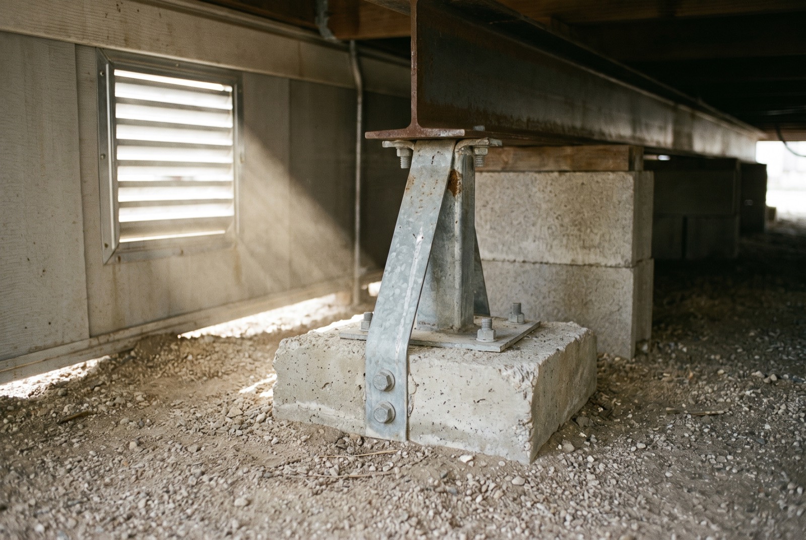
PFGMH stands for the Permanent Foundations Guide for Manufactured Housing. It is HUD's engineering reference for the structural conditions that convert a manufactured home from chattel to real property. HUD 4000.1's first finding (F1) defers to PFGMH § 3. This page is the deep reference on what § 3 actually requires.
A manufactured home is delivered to a site as personal property — chattel, in the legal sense. It rolls in on its own running gear; the steel frame and axles together are designed to carry the home over the road. At delivery, it is not real estate.
For most affordable-housing finance products — FHA, conventional Fannie/Freddie, USDA Rural Development — the home must be converted from chattel to real property before the financing can attach. The conversion happens through two parallel actions: (1) the home is physically set on a permanent foundation meeting HUD's engineering criteria, and (2) the home's title is surrendered to the state and re-recorded as part of the real property (the "affixation" process).
PFGMH § 3 governs the engineering side. It specifies the structural conditions that constitute a permanent foundation. Without compliance with § 3, the home remains chattel in HUD's eyes, regardless of how long it's been sitting in place or how integrated it appears. Long-term mortgage financing requires permanence; permanence requires PFGMH § 3.
"A permanent foundation shall be constructed of durable materials — concrete, mortared masonry, or treated wood — and be site-built. It shall have attachment points to anchor and stabilize the manufactured home to transfer all loads, defined herein, to the underlying soil or rock."
"The foundation shall be capable of supporting the dead loads of the home and the live, wind, and seismic loads for the home's installation location, in accordance with the relevant ASCE 7 design parameters."
The pier system is the structural element between the home's main steel I-beams (the frame the home was transported on) and the footings buried in the ground. Each pier transfers vertical dead and live load down to its footing, and resists lateral loads through anchoring and frame attachment.
PFGMH § 3.2 allows several pier types, each with specific construction requirements:
Pier spacing along the home's main I-beams is determined by the home's design loads — published on the data plate — and the local site conditions. Default maximum spacing is 6′0″ on center along each I-beam, with closer spacing at corners and intermediate beam supports. Wind-zone-II and -III sites typically require closer spacing.
| Location | Typical spacing | Notes |
|---|---|---|
| Main I-beam piers | 6′0″ o.c. max | Reduced to 4′0″ in higher wind zones |
| Marriage-line piers (double-section) | 6′0″ o.c. max | Under the line where the two halves join |
| Perimeter piers | 6′0″ o.c. max | Outer rim joist support |
| End piers | Within 2′ of end wall | Both ends, both I-beams |
| Concentrated load piers | As required | Under wood stoves, fireplaces, bay windows |
Each pier must make positive contact with the home's main I-beam through a properly sized cap plate — a wood or metal plate that transfers load from the pier top to the bottom flange of the I-beam. The cap plate must not be crushed, fractured, or shifted off-center.
Gaps between pier top and I-beam — even small ones — indicate the home has moved relative to the pier (typically settlement of the pier, or uplift on under-anchored homes during wind events). Gaps must be shimmed properly or the pier reset. Random scrap wood, plywood shims, or sheet-metal flashing stuffed into gaps will not be accepted.
Footings are the concrete or masonry bases beneath each pier. They spread the pier's vertical load over a larger area of soil so that the soil bearing pressure stays below the soil's capacity, and they extend below the local frost line so that seasonal frost heave doesn't displace the pier.
Footing size is a function of pier load and soil bearing capacity. PFGMH provides default sizing tables based on an assumed 1,500 psf soil bearing capacity — a conservative value that works for most Midwest soils outside of saturated clays or organic soils.
PFGMH allows the engineer to assume default soil bearing if no specific soil report is available — typically 1,500 psf for residential sites in undisturbed natural soils. Visible signs of soft soil (organic matter, prior fill, seasonal wet spots) require either a soil report or oversized footings to compensate. Footings set directly on fill that wasn't compacted are a common F1 failure — easy to spot, and the remediation is straightforward (excavate, set on undisturbed soil with proper bedding).
Ground anchors and tie-down straps connect the home's steel frame to the earth below the foundation. Their job is to resist uplift, overturning, and lateral loads during wind events — the loads that would otherwise lift, slide, or rotate the home off its piers.
The strap geometry — angle of the strap relative to the home and ground — affects how loads transfer. PFGMH specifies allowed strap angles for each anchor configuration, typically between 25° and 45° from vertical. Straps installed at angles outside the allowed range can't develop their rated holding capacity and constitute an F1 finding.
Each strap attaches to the home's main I-beam through a frame bracket or wraps over the top of the I-beam and re-secures to itself. Attachment hardware must be galvanized or otherwise corrosion-resistant; raw-steel attachments showing rust scale will be flagged.
Skirting forms the perimeter enclosure around the crawl space between the home and the ground. It serves multiple structural and habitability functions: protecting the underside of the home from wind, rain, and pests; defining the crawl space envelope for moisture management; and providing the visual completion of the home-to-ground transition.
PFGMH § 3.6 requires durable materials for skirting:
The crawl space requires cross-ventilation through the skirting to manage humidity. Typical requirement: vent area equal to 1/150 of the crawl space floor area (with a 1/1500 reduction if a vapor barrier is installed, which is the standard practice). Vents must be distributed around the perimeter, not concentrated on one side.
At least one removable access panel must be provided in the skirting, typically 18″ × 24″ or larger. This is where the next inspector (or repair technician) enters the crawl space; if it doesn't exist, F5 fails.
A continuous polyethylene vapor barrier (6-mil minimum) covers the ground inside the skirting perimeter to limit moisture migration from the soil into the crawl space. Seams overlap 12″ minimum; barrier extends up the inside of the skirting 4″ to 6″. Torn, missing, or animal-damaged vapor barrier is a common F5 finding — remediation is straightforward.
PFGMH § 3.5 requires that the running gear — axles, wheels, tires, and the hitch assembly — be removed from the home as part of the permanent-foundation conversion. The PFGMH wording is "removal"; most underwriters will accept documentation that the running gear has been transported off-site and stored separately.
The structural logic is that a permanent foundation must transfer loads to soil through the pier-and-footing system — not through the home's axles. The eligibility logic is that a "permanent" foundation cannot have ready means of mobilizing the home. Wheels in storage on-site, hitches still welded to the frame, or axles propped against the rear of the home all constitute F6 findings.
Remediation: relocate the components off-site (a neighbor's barn or a self-storage unit is acceptable; the dealer often will take them), cut the hitch off (it's a welded steel assembly, requires a torch or angle grinder), and document the removal photographically. The PE re-visits or accepts seller-provided photos depending on the timeline.
PFGMH § 3 compliance is the engineering half of converting a manufactured home from chattel to real property. The legal half — equally important for FHA insurability — is the affixation process: surrendering the home's title (issued by the state DMV or DOR) and re-recording the home as part of the real property described in the deed.
Both halves must complete for FHA financing to attach. PFGMH § 3 compliance gets the structural finding; affixation gets the title finding. A home with a textbook permanent foundation but no completed affixation document is still chattel from FHA's perspective. See the Affix Report practice for the document side; this site handles the structural side.
The practical implication for an active pipeline: confirm both work streams are running in parallel. Most title issues surface late and cause more delays than structural findings. If the home has been on its current foundation for years without an FHA loan against it, there's a meaningful chance the affixation paperwork was never completed even if the foundation looks fine.
Drop the property address, FHA case number, and timeline. Acknowledgment within one business day. Written quote same business day. Field visit confirmed within 24 hours. PE-sealed PDF in your underwriter's file in 24 hours from field visit.
FHA structural reports here; manufactured-home inspections, affixation documents, and aluminum wiring certifications through the rest of the firm. One engineer of record, licensed in seven states.
Visit the firmA new conventional financing path may require a post-move structural integrity inspection.
Get the moved-home structural integrity report →